
HSRP – MHSRP – HSRP with BFD
MHSRP stands for Multiple HSRP Groups. It is an extension of HSRP that uses multiple HSRP groups to distribute the active gateway role across different routers instead of having one router handle all first-hop gateway traffic.
In this article, we will review standard Cisco HSRP, explain how MHSRP works, compare HSRP and MHSRP, and finally look at how BFD can be used with HSRP for faster failure detection.
Table of Contents
What Is HSRP?
HSRP, or Hot Standby Router Protocol, is a First Hop Redundancy Protocol used to provide default-gateway redundancy.
- HSRP provides gateway availability through redundant devices.
- HSRP is categorized as an FHRP, or First Hop Redundancy Protocol.
- HSRP is Cisco-specific, unlike VRRP, which is an open standard.
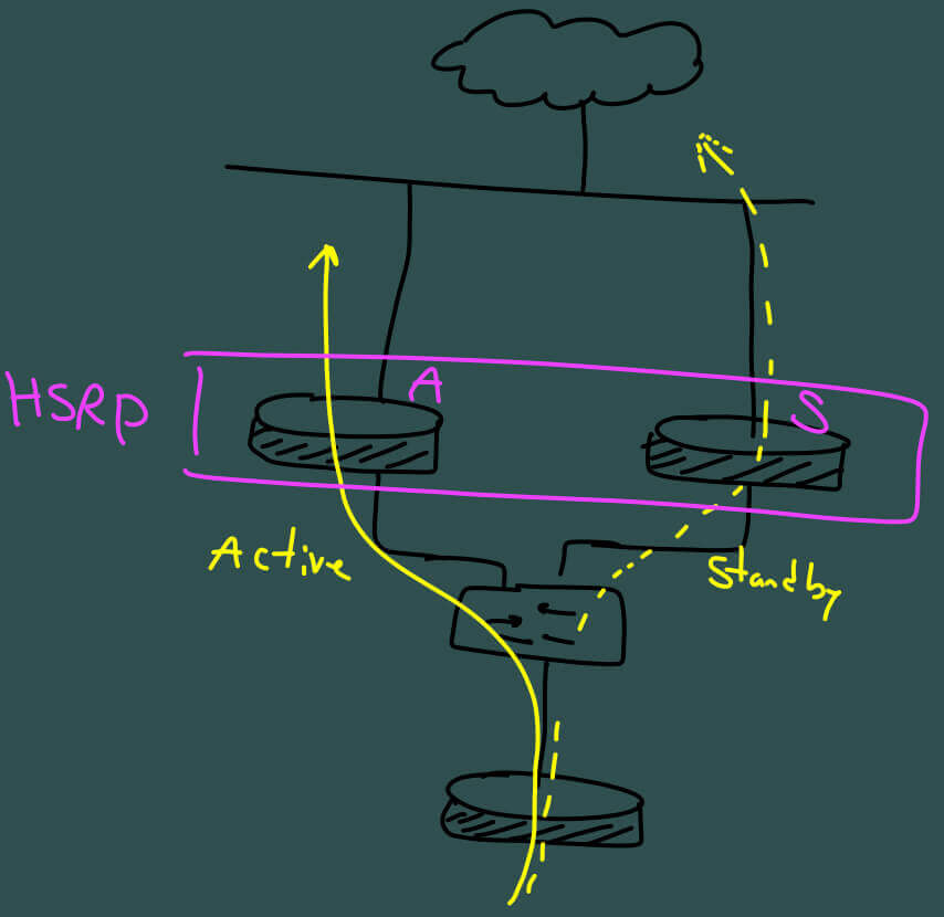
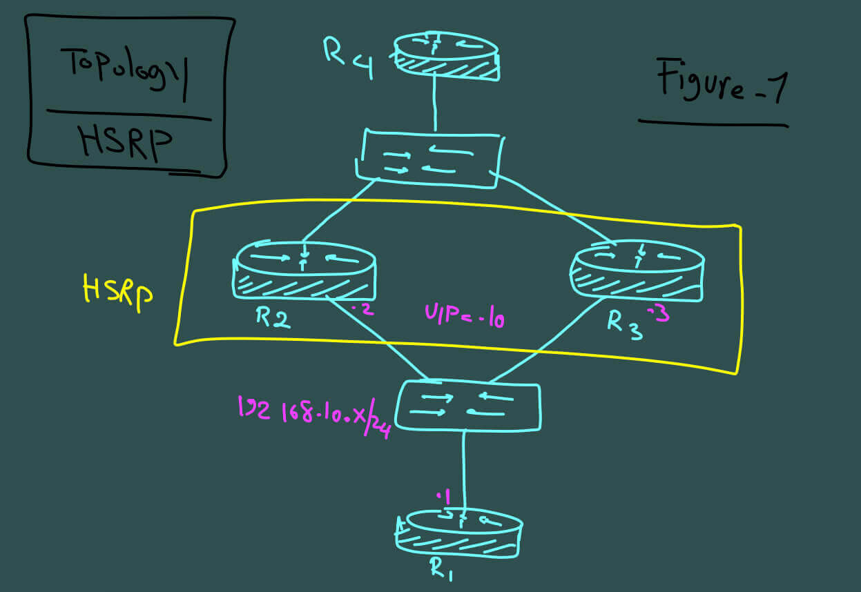
A group of routers participates in one HSRP group and presents itself to end hosts as a single virtual router.
The group shares:
- A virtual IP address
- A virtual MAC address
One router operates as the Active device, while another router operates as the Standby device.
If the Active router fails, the Standby router takes over the gateway role.
HSRP Design Considerations
When deploying HSRP on multilayer switches, the Spanning Tree topology and HSRP gateway roles should be aligned.
Ideally, the switch acting as the HSRP Active gateway should also be the preferred Layer 2 forwarding path for the corresponding VLAN.
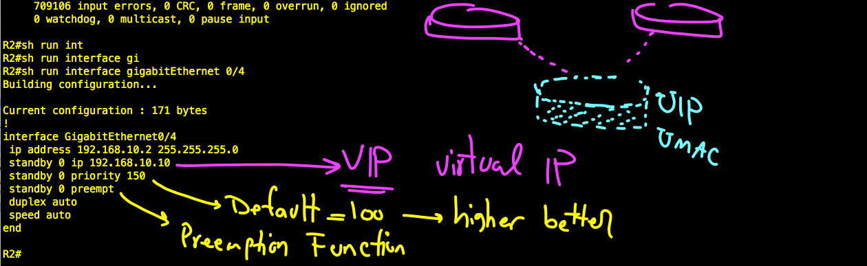
HSRP preemption is important in this design because it allows the preferred router to regain the Active role after recovering from a failure.
A preemption delay should also be considered. Without a delay, a router may become Active before all interfaces, routes, and forwarding functions are fully operational, which can temporarily create a traffic black hole.
HSRP Configuration
HSRP Configuration on R2
The following example shows the HSRP configuration under the interface of R2.
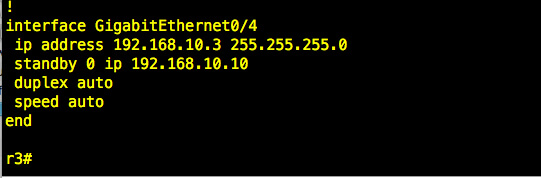
HSRP Configuration on R3
The following screenshot shows the HSRP interface configuration on R3.
HSRP Verification
The first useful verification command is:
show standby brief

For more detailed information, use:
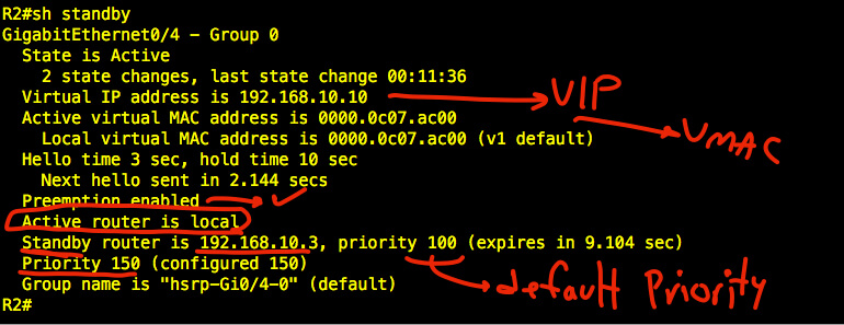
show standby
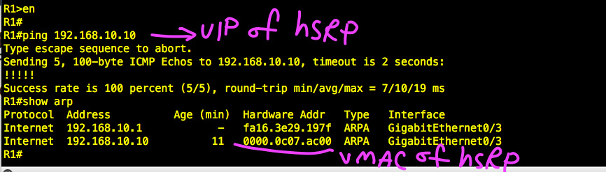
We can also verify the virtual gateway from R1 by checking connectivity and ARP information.
MHSRP Meaning
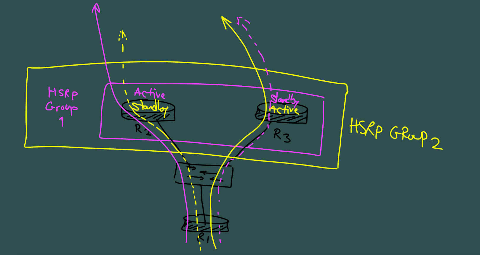
MHSRP means Multiple HSRP Groups. Instead of using only one HSRP group, MHSRP creates multiple groups so that different routers can be Active for different groups.
MHSRP is useful for load sharing. It is important to distinguish this from per-packet or per-flow load balancing. Different traffic destinations or gateway references can be directed toward different HSRP groups.
In this lab, two HSRP groups are created:
- R2 is Active for HSRP Group 1.
- R3 is Standby for HSRP Group 1.
- R3 is Active for HSRP Group 2.
- R2 is Standby for HSRP Group 2.
This allows both routers to participate actively in forwarding traffic instead of leaving one router idle during normal operation.
MHSRP Configuration
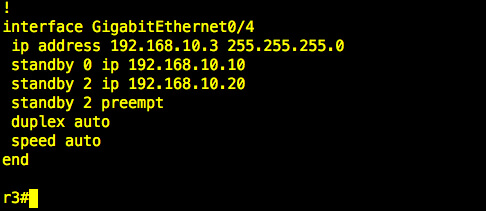
The following screenshots show the multiple HSRP group configuration on R2 and R3.

After configuration, verify the HSRP group states on both routers.

MHSRP Load Sharing
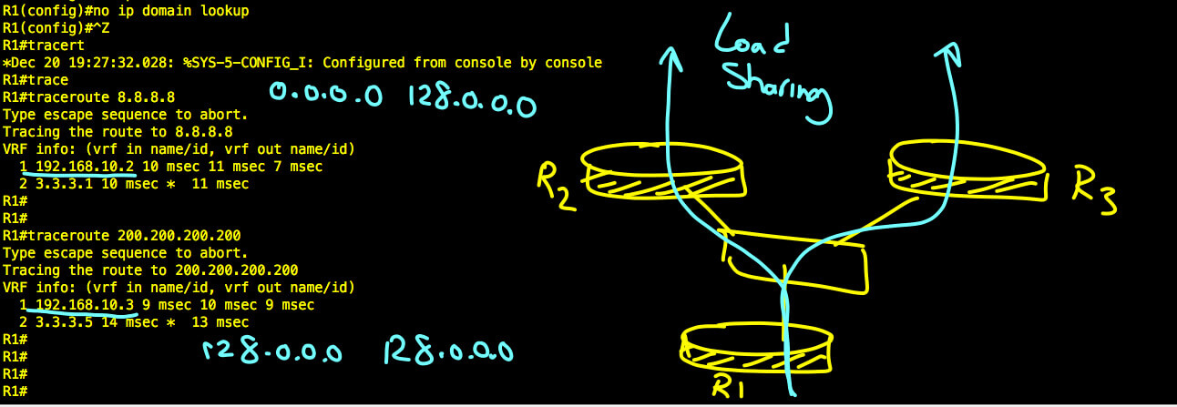
One way to demonstrate MHSRP load sharing is to divide the IPv4 default route into two large prefixes and send each prefix toward a different virtual gateway.
The first half of the IPv4 address space can be routed toward R2:
0.0.0.0 128.0.0.0 via 192.168.10.10The second half can be routed toward R3:
128.0.0.0 128.0.0.0 via 192.168.10.20This demonstrates how different traffic can use different HSRP groups and therefore different Active routers.
HSRP vs MHSRP vs HSRP with BFD
| Feature | HSRP | MHSRP | HSRP with BFD |
|---|---|---|---|
| Main Purpose | Default gateway redundancy | Gateway redundancy plus load sharing | Faster failure detection for HSRP |
| HSRP Groups | Usually one group per gateway design | Multiple groups | One or more groups |
| Active Routers | One Active per group | Different routers can be Active for different groups | One Active per group with faster peer-failure detection |
| Load Sharing | Not inherently | Yes, across multiple HSRP groups | Not the primary purpose |
| Failure Detection | HSRP hello/hold timers | HSRP hello/hold timers per group | BFD-assisted fast detection |
| Typical Use | Simple gateway redundancy | Use both redundant routers during normal operation | Reduce convergence time when a forwarding path fails |
Use Cases
Standard HSRP
Use standard HSRP when the primary requirement is simple default-gateway redundancy and having one Active gateway per HSRP group is sufficient.
MHSRP
Use MHSRP when you want to keep gateway redundancy while also making better use of multiple routers during normal operation.
Typical examples include:
- Different VLANs using different Active gateways
- Different subnets using separate HSRP groups
- Distributing traffic across two redundant distribution switches
- Avoiding a design where one gateway device remains mostly idle
HSRP with BFD
Use HSRP with BFD when fast failure detection is important and waiting for standard HSRP timers may introduce too much convergence delay.
HSRP with BFD
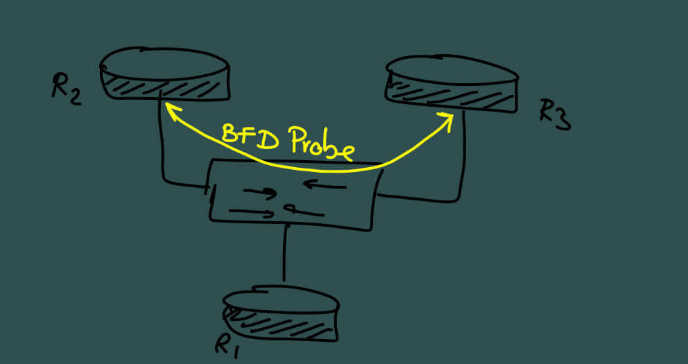
BFD, or Bidirectional Forwarding Detection, can be used together with HSRP to provide faster detection of forwarding-path failures.
HSRP normally relies on its own protocol messaging and timers to monitor peers. BFD provides a lightweight mechanism designed specifically for rapid path-failure detection.
This can reduce convergence time and allow HSRP to react more quickly when the monitored forwarding path fails.
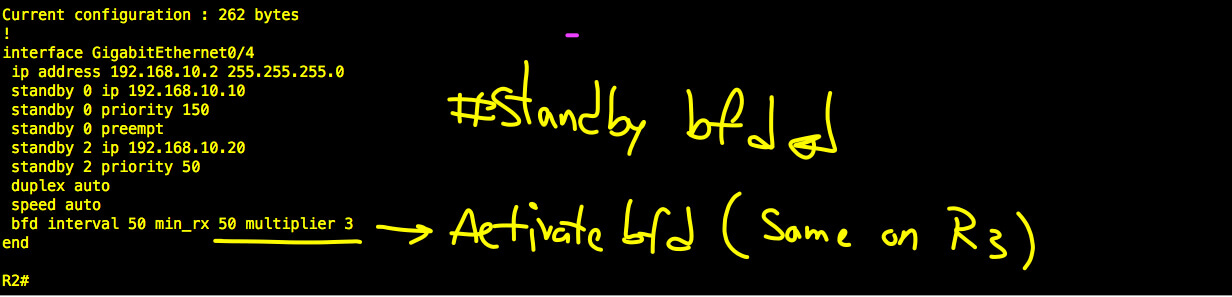
HSRP with BFD Configuration
The following screenshot shows the configuration used in the lab.
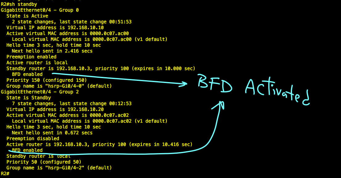
Verify HSRP with BFD
Verify the HSRP state using:
show standby
Conclusion
HSRP provides first-hop gateway redundancy by presenting a virtual gateway to end devices. MHSRP extends that design by using multiple HSRP groups, allowing different routers to be Active for different groups and making load sharing possible.
HSRP with BFD addresses a different requirement: faster failure detection. BFD can help HSRP respond more quickly to forwarding-path failures without changing the fundamental Active and Standby gateway model.
For the query MHSRP meaning, the key point is simple: MHSRP means Multiple HSRP Groups, and its main benefit is distributing gateway responsibility across multiple redundant routers.
Download the HSRP PDF
You can also download the HSRP PDF version for offline reference. It covers HSRP, MHSRP, and HSRP with BFD concepts and configuration examples.